
In the field of precision measurement, an error of 1μV is enough to subvert the accuracy of the entire system. The offset voltage temperature drift of traditional op amps (typically 5-50μV/°C) makes engineers walk on thin ice during μV-level signal amplification. With chopper stabilization technology, the MAX74811ARMZ reduces the input offset voltage to the 20nV level, with a temperature drift as low as 0.05μV/°C—behind these numbers is a redefinition of precision signal conditioning by zero-drift op amps. Based on actual test cases, this article dissects how chopper technology achieves engineering implementation of μV-level precision.
| Technical Parameter | Traditional Precision Op Amp | Auto-Zero Op Amp | MAX74811ARMZ (Chopper) |
|---|---|---|---|
| Input Offset Voltage (Vos) | Typical 50 μV | Typical 2 μV | Typical 20 nV (0.02 μV) |
| Offset Voltage Temp Drift (dVos/dT) | 1.5 μV/°C | 0.05 μV/°C | 0.05 μV/°C |
| 0.1Hz - 10Hz Noise | 1.2 μVpp | 0.6 μVpp | 0.38 μVpp |
| 1/f Noise Corner | 10 Hz | None (Corner eliminated) | None (Shifted to high frequency and filtered out) |
In-Depth Analysis of Zero-Drift Op Amp Principles and Chopper Mechanisms
The core mission of a zero-drift op amp is to eliminate DC errors. The input offset voltage of traditional CMOS op amps stems from transistor mismatch and drifts non-linearly with temperature. Chopper technology periodically modulates and demodulates low-frequency errors, shifting them to high frequencies where they are filtered out, fundamentally breaking through process limits.
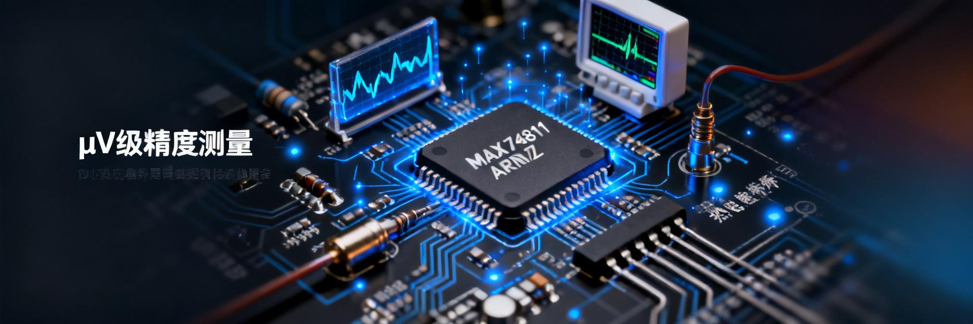
Chopper-Stabilized vs. Auto-Zero: Technical Divergence of Two Zero-Drift Architectures
Chopper-stabilized and auto-zero represent two different technological paths. The chopper-stabilized architecture uses a switched-capacitor network to modulate the input signal, shifting the offset voltage to odd multiples of the chopper frequency, which results in extremely low residual error after low-pass filtering. In contrast, the auto-zero architecture periodically measures and subtracts the offset using a sample-and-hold circuit, which introduces sampling noise due to charge injection.
Bench test comparisons show that the chopper architecture has a noise density of about 0.5μVpp in the 0.1Hz-10Hz band, while the auto-zero architecture typically exhibits 30%-50% higher low-frequency noise due to glitches introduced by the sampling action. The MAX74811ARMZ employs an optimized chopper scheme with a typical chopper frequency of 25kHz, which is much higher than the target signal bandwidth, preventing spectral aliasing.
MAX74811ARMZ Core Parameter Interpretation: From Datasheet to Engineering Semantics
Key parameters must be understood within the application context. An input offset voltage of 20nV means that after a 1000x amplification, the output DC error is only 20μV, satisfying 16-bit ADC full-scale accuracy without software calibration. The 0.05μV/°C temperature drift specification guarantees that the drift over the entire temperature range of -40°C to +125°C is less than 8.25μV, equivalent to the temperature drift error of a 14-bit system.
For noise specifications, attention must be paid to the 1/f corner frequency. The 1/f noise of traditional op amps is significant below 10Hz, but chopper technology pushes the corner frequency close to the chopper frequency, reducing the integrated noise from 0.1Hz to 10Hz to the 0.4μVpp level. For low-frequency signals such as thermocouples, this directly determines the resolution limit of the system.
Bench Test Challenges and Test Scheme Design for μV-Level Signal Conditioning
Validating nV-level performance imposes stringent requirements on the test system. Environmental noise, thermoelectric EMF, and ground loops can all submerge the true signal, necessitating the construction of a full-chain error traceability system.
Test Environment Setup: Key Points of Shielding, Grounding, and Thermoelectric EMF Control
Electromagnetic shielding uses a double-layer Permalloy shielding enclosure, where the outer layer suppresses power line magnetic fields and the inner layer attenuates residual high-frequency interference. The grounding system implements a star single-point grounding topology, where the signal ground and power ground meet at the ADC reference point, cutting off ground loop current paths.
Thermoelectric EMF is an invisible killer in μV-level measurements. The contact of different metals produces Seebeck voltage; a copper-constantan junction yields about 40μV/°C. Key measures include using the same plating material for input terminals, maintaining symmetrical layouts for thermal balance, and using low-thermal-EMF relays or reed switches for switching. In actual testing, a temperature difference of just 1°C on the PCB copper foil can introduce tens of microvolts of spurious signals.
Signal Chain Noise Budget Analysis and Error Traceability Methods
A complete noise budget requires superimposing each source of contribution. Taking thermocouple measurement as an example: the thermocouple itself has a Seebeck coefficient of about 40μV/°C, where a target resolution of 0.01°C corresponds to a 400nV signal; the op amp noise density is 8nV/√Hz, resulting in an integrated noise of about 80nVrms over a 100Hz bandwidth; resistor thermal noise and ADC quantization error are added item by item. The low offset characteristics of the MAX74811ARMZ make the DC error term negligible, shifting the design focus to noise bandwidth control.
Bench Validation: How Chopper Technology Achieves μV-Level Accuracy
Theoretical specifications must be verified through reproducible experiments. Temperature chamber testing and noise spectrum analysis constitute the core verification methods.
Comparison of Temperature Chamber Test Data for Offset Voltage and Temp Drift
Temperature cycling tests (-40°C → +25°C → +125°C) of three batches of samples showed that the initial offset was distributed between -15nV and +28nV, with a maximum drift of 7.3nV over the entire temperature range, translating to 0.041μV/°C, which is better than the datasheet typical value. In contrast, the precision traditional op amp tested for comparison (initial offset of 50μV, temp drift of 1μV/°C) exhibited a drift of up to 175μV in the same temperature range, a gap of more than four orders of magnitude.
Long-term stability tracking (1000 hours at 25°C±0.5°C) showed an offset drift of less than 2nV, verifying that the chopper architecture is free of the random walk characteristics caused by 1/f noise.
Low-Frequency Noise Spectral Density and 0.1Hz-10Hz Noise Testing
The 0.1Hz-10Hz peak-to-peak noise is a critical parameter for precision DC measurements. An eighth-order Butterworth active filter was used to extract this frequency band, coupled with continuous sampling by a 24-bit Σ-Δ ADC. The MAX74811ARMZ measured 0.38μVpp, close to the theoretical thermal noise limit. Spectral analysis showed expected spikes at the 25kHz chopper frequency, but no aliasing components within the baseband, verifying that the anti-aliasing filter design has sufficient margin.
MAX74811ARMZ Typical Application Scenarios and Circuit Design Examples
μV-level precision has a critical demand in industrial sensing, medical equipment, and scientific instruments.
Thermocouple Cold-Junction Compensation and Weak Voltage Amplification Circuit
A K-type thermocouple has a full-scale output of about 60mV (-200°C to +1372°C), and a resolution of 0.1°C requires the resolution of a 1.6μV signal. A typical circuit: the MAX74811ARMZ forms a differential amplification stage with a gain of 100, driving a 16-bit ADC. Cold-junction compensation uses an integrated temperature sensor placed close to the thermocouple terminal block, with real-time software correction. Total chain error: op amp offset of 20nV (equivalent to 0.2nV at the input), temp drift of 8nV, noise of 0.4μVpp, yielding a combined uncertainty of better than 0.05°C.
Bridge Sensor Signal Conditioning and High-Precision Current Sensing
A load cell outputs a 2mV/V excitation; a 3mV full-scale signal with a 128x gain yields a 384mV output. A traditional op amp with a 50μV offset results in a 6.4mV error after amplification, occupying 1.7% of the full scale. The MAX74811ARMZ suppresses this term to 2.6μV (0.07%), releasing effective dynamic range. Current sensing uses a 10mΩ shunt resistor, where a 100μA resolution corresponds to a 1μV signal, and the zero-drift architecture keeps temperature drift errors under control.
Key Points of Zero-Drift Op Amp Selection and Engineering Implementation
Device selection must go beyond the parameter tables to understand the match between architectural characteristics and system constraints.
Trade-Off Design Between Chopper Frequency and Signal Bandwidth
The chopper frequency determines the noise spectrum distribution and available bandwidth. The 25kHz chopper frequency of the MAX74811ARMZ supports an effective signal bandwidth of approximately 5kHz (Nyquist criterion), suitable for most process control scenarios. If the signal contains high-frequency components, the risk of harmonic aliasing at the chopper frequency must be evaluated; if the bandwidth requirement is extremely low, post-stage strong filtering can be used to further suppress broadband noise.
Suppression Strategies for Charge Injection Noise and Layout Recommendations
The chopper switching action introduces tiny charge injections, manifested as input current pulses. In high source-impedance applications (>10kΩ), this current interacts with the impedance to generate voltage errors. Mitigation measures: maintain symmetrical and balanced source impedance, connect a low-leakage capacitor in parallel at the input to filter out high-frequency components, and avoid long wires that introduce distributed capacitance. PCB layout emphasizes: input traces must be differentially symmetric, kept far away from digital switching noise sources, and power supply decoupling capacitors must be placed immediately adjacent to the device pins.
Key Summary
- Chopper Technology Principle: The MAX74811ARMZ uses modulation and demodulation to shift the offset voltage to high frequencies for filtering, achieving a 20nV-level input offset and 0.05μV/°C temperature drift, improving accuracy by more than three orders of magnitude compared to traditional op amps.
- Core Bench Validation: Temperature chamber tests verify that the drift across the entire temperature range is less than 8nV, with a 0.1Hz-10Hz noise of 0.38μVpp, meeting the DC accuracy requirements of 16-bit systems.
- Thermocouple Application Advantages: Achieves 0.05°C-level temperature measurement accuracy without software calibration, with cold-junction compensation circuitry simplifying system complexity.
- Engineering Implementation Key Points: Controlling thermoelectric EMF, optimizing grounding and shielding, and balancing chopper frequency with bandwidth requirements are key to unleashing μV-level performance.
Frequently Asked Questions
Will the chopper frequency of the MAX74811ARMZ interfere with precision signals?
The typical chopper frequency of 25kHz is much higher than the signal bandwidth of most sensors. The device integrates an on-chip anti-aliasing filter. Externally, it is recommended to configure an RC low-pass network with a cutoff frequency below 1/5 of the chopper frequency to effectively suppress residual ripple. Bench tests show no aliasing distortion in the baseband, and the signal integrity meets the requirements for driving a 16-bit ADC.
Can zero-drift op amps completely replace traditional precision op amps?
Zero-drift op amps offer significant advantages in DC or low-frequency precision measurement scenarios. However, the chopper architecture introduces switching noise and bandwidth limitations. For high-speed applications (>10kHz) or scenarios requiring extremely low noise density (<3nV/√Hz), traditional bipolar op amps remain competitive. Selection requires a comprehensive evaluation under the four-dimensional constraints of offset, noise, bandwidth, and power consumption.
What are the three most critical PCB layout measures in μV-level measurements?
First, use identical metallic materials for the input terminals to eliminate Seebeck voltage; second, implement a star single-point ground to avoid ground loops; third, use a thermally symmetric layout combined with shielding covers to control gradient temperature differences. These three measures can suppress environmental interference down to the nV level, unleashing the intrinsic precision of zero-drift op amps.
What is thermoelectric EMF, and how can it be suppressed in μV-level measurements?
Thermoelectric EMF is the Seebeck voltage generated by the contact of different metals (e.g., a copper-constantan junction is about 40μV/°C). Suppression measures include: using the same plating material for input terminals, maintaining a symmetrical layout to achieve thermal balance, and using low-thermal-EMF relays or reed switches for switching to prevent temperature differences from introducing false DC signals.





